

Let’s get down to business, the hard truth, and everything you need to know.
Technical
THE GATEWAY TO DRIVING PLEASURE & POWER
No air means, no fun and no power. It is as simple as that. The throttle body is perhaps the most important control in an internal combustion engine. Driving pleasure and power depend on the throttle body characteristic curve, this is the time and manner in which air is allowed into the engine. It can be made sluggish and economical or vigorous and responsive. Unfortunately for some, a sluggish response, although economical, is not desirable. Even more so in the case of a high-performance sports car. If you feel this way then this product is right for you.
Furthermore, it is arguably the most cost-effective upgrade you can make to your vehicle. It is an easy noticeable/measurable modification that requires no special skills/tools and takes only 15 minutes or less of your time.
WE OUTPERFORM THE COMPETITION: OEM 100%, PTB over 50% up to 70% Airflow gains at part throttle!
DON’t believe us, MEASURE IT YOURSELF!
SE8223-100 and SE9871-100 Premium Modified, Ported, and Calibrated Throttle Body (NEW).
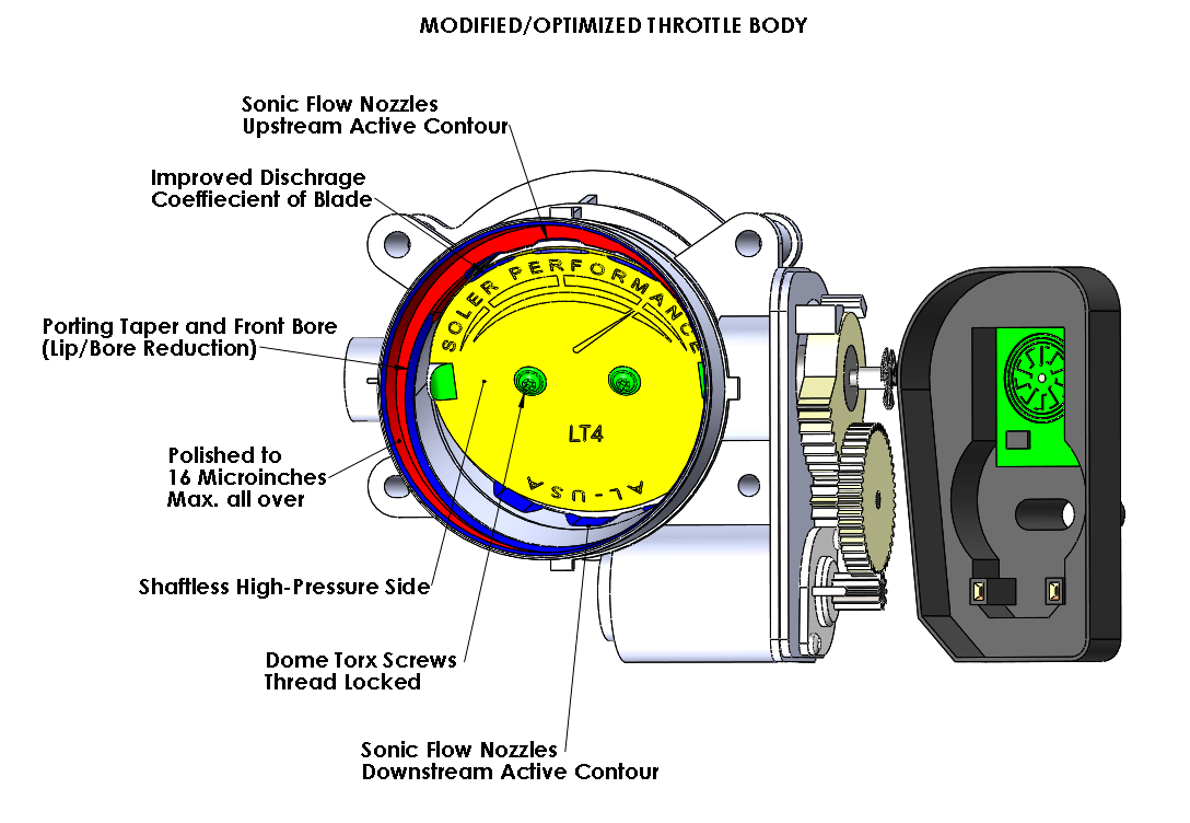
FEATURES:
• Optimized Active Contours (Both Upstream & Downstream)
• Porting Taper and Upstream Bore (Lip & Bore Reduction)
• Greater Discharge Coefficient of Plate/Blade
• 16 Ra Microinch, Diamond Polished Surface Finish (Lower Skin Friction)
• Shaftless High-Pressure Side for increased air flow; Part Throttle all the way up to WOT (91 mm effective LT1/LT4 and 100 mm effective LT5)
• Self-Cleaning Throat/Flow Gap
• Minimized Gear Backlash
• Dome Torx Screws, Thread Locked
• Higher Quality
• Made from Brand New OEM Parts
BENEFITS:
• Lower weight to power ratio at part throttle, for a more nimble/spirited driving experience
(We doubled the rate of change of mass airflow (MAF) from 1.2 g/s-deg to 2.4 g/s-deg) , 100% Increase!
• Linearization and smoothing of the curve for a more predictable response and crisper shifts
• Immediate response right off idling while keeping idling function undisturbed (No Hesitation/Stumble)
• More air/power at every single throttle position after idle. Crucial for starting or expanding power gain modifications
• Easy Installation
Keep reading below if you are interested in the intrinsic details and to further expand your knowledge within this modification.
expand your knowledge:
our goal
The SE8223-100 throttle body is a modification of the ACDelco (GM) p/n 12678223 throttle body. This part is used in several recent model years of GMC automobiles listed on table 1. The objective of the modification is to change the mass air flow (MAF) rate vs. throttle percent characteristic curve to achieve the following performance features:
• Lower weight to power ratio at part throttle, for a more nimble/spirited driving experience
• Linearization and smoothing of the curve for a more predictable response
• Immediate response right off idling while keeping idling function undisturbed
Development of the modified throttle body originated from observations and testing made on a 2015 Chevrolet Corvette Stingray (6.2 L engine, naturally aspirated). This particular vehicle presented the following issues:
• Slow throttle response in the 0-30% range of throttle position, steep response in the 30-100% range
• Relatively underpowered in the 0-30% range of throttle position

Table 1. Model years using throttle body. This part also supersedes p/n 12620263 used in earlier models (i.e. MY 14/15/16 Corvettes).
Investigation
An in-depth investigation was carried out by Soler Performance LLC. The objectives of the investigation were the following:
• Reverse engineer OEM and aftermarket throttle bodies geometries
• Measure/plot MAF vs. throttle position of OEM throttle body and several leading aftermarket ported throttle bodies
• Flow test OEM and aftermarket throttle bodies
• Perform computational fluid dynamic (CFD) simulations of OEM and aftermarket throttle bodies
• Compile the data and validate perceived issues
• Find root cause for the issues
• Develop a design and manufacturing approach to overcome the issues
NOtE: P/N SE8223-100 throttle body fits all C7 corvettes 2014-present (except the zr1). table 1 is only a partial list of eligible vehicles (the actual list is much larger). FOR ZR1 see SE9871-100.
NEW: Camaro (6th Generation) SS & ZL1 AND Cadillac CTS-V are NOW AVAILABLE FOR PURCHASE!
Throttle Body Basics
The throttle body is a butterfly type valve that regulates the amount of air entering an internal combustion engine in proportion to the accelerator pedal position. It is the main control of engine power as the amount of air permitted into the engine defines a limited amount of fuel that can be burned in the combustion chamber hence the amount of energy released by the fuel. It is part of the air induction system, commonly listed as a component of the fuel system as well. It is located downstream of the air filter and upstream of the intake manifold.
More specifically, the throttle valve regulates the pressure in the intake manifold via a pressure drop caused by the gap (restriction) between the throttle plate and the active contour of the throttle body which in turn regulates the air density inside the manifold. At low throttle plate angles the pressure drop is high and the manifold air pressure (MAP) is low, the opposite occurs at high throttle plate angles. The air density inside the intake manifold is proportional to the MAP and because the volume of air admitted into the combustion chamber and the vacuum created during intake stroke is predefined by the engine displacement and rpm, then the total mass of air admitted is limited by the air pressure/density in the intake manifold.


Figure 5. Typical electronic throttle control (ETC) diagram.
The throttle body of this application is of the electronic control type also known as drive-by-wire, in which, the accelerator pedal sends a signal to the powertrain/engine control module (PCM/ECM) and the ECM signals the throttle the opening percent (throttle position) required based on various parameters also relied to the PCM/ECM by other systems/sensors. The accelerator pedal assembly requests the PCM/ECM the desired throttle position through the APP, then, an algorithm in the PCM/ECM calculates the required throttle position which is sent to the throttle motor. The motor moves the throttle plate/blade and the throttle position sensor detects and relays the actual position back to the PCM/ECM, the algorithms run again until desired position and actual position converge, closing the control loop in this manner.
The TAC system operates in different modes including but not limited to:
Normal
Cruise control
Ice break
Battery Saver
Acceleration limiting
Forced idle
Engine shut down

Figure 6. GM/AC Delco p/n 12678223 throttle valve main components. View from the air inlet side and with cover removed
Reverse Engineering
A total of 10ea new throttle valves GM/AC Delco p/n 12678223 from different manufacturing lots were reverse engineered using a coordinate measuring machine and other high precision measuring devices in order to create an average solid model representative of the nominal GM part geometry (OEM). Four different aftermarket brands throttle bodies made from new OEM’s were also reverse engineered for the same purpose.
• Body: Cast Aluminum alloy, provides structural support for other components and means for attachment to NHA. It defines the flow path for mass flow rate regulation in combination w/ plate.
• Shaft: Steel alloy, provides structural and locational support for the plate, drives sensor target rotor and it is driven by the sector gear.
• Plate/Blade: Defines flow path in combination w/ body internal contour, regulates air flow.
• Torsion Springs: Position plate on a default/limp position (30°) preload and balance torque load on the shaft.
• Torque Motor: Induction, brushed, 8 wound rotor poles, 2 permanent magnet stator poles, provides 2-5 ozf-in torque at 3-5 V to reduction gear thru pinion (Np=10). Provides torque required to move and hold the plate at the desired position.
• Reduction Gear: (No=46, Nf=10) multiplies motor torque by providing a total transmission ratio of 21.16 from pinion to sector gear (Ns=46) and shaft.
• Close/Open Stops: Limits plate travel through contact w/ sector gear closed (0°), open (90°).
• Sensor Target: Rotates with shaft and faces inductive sensor to create an inductive effect on sensor windings that signal actual plate position to ECM.
• Inductive Sensor: A set of coils printed on a circuit board. The transmitter coil induces a voltage on receiver coils as a function of target/rotor angular position, indicating actual plate position/angle.
• ECM Connector: Brings power and signals from and to the ECM for closed-loop control of plate or airflow.

Figure 7. OEM average nominal cross section showing different operating regions.
Operating Regions
Cold Idle: Set to control the idle speed at 1100 rpm Max. to 650 rpm depending on temperature. Flow is choked/limited at plate/active contour (red) interface.
Hot Idle: Set to control the idle speed at 650 rpm once the engine is at a suitable operating temperature. Flow is choked/limited at plate/active contour (red) interface.
Limp Mode: Set by default by equilibrium/preload of torsion springs and used to provide a limited amount of air, for enough power to drive when throttle valve malfunctions.
Power Driving: Characterized by a high flow rate where active contours (red) become inactive as they don’t interface effectively with the plate. Flow is mainly restricted downstream at intake valves, hence the manifold pressure is nearly equal to the ambient pressure.
Part Throttle Driving: Occurs between idle throttle position (~5°) and the end of the active profile (~35°). It accounts for about 1/3 of the valve range and it is where most of the driving occurs. This region is characterized by the close proximity between the plate and the body defining a narrow flow gap to restrict/control air flow. In this regime, most of the air induction system pressure drop occurs. Airflow reaches a sonic speed at this location and does not respond to manifold pressure (vacuum). Flow is totally dependent on upstream pressure and more importantly on the area defined by the flow gap.

Figure 8. Throttle valve active contours.
ACTIVE CONTOUR
Active Contour: The active body contour (red) is composed of a central cylindrical surface (87 mm bore) from which tangent ellipsoidal surfaces extend forward on the upper side and aft on the lower side and ending in respective cylindrical surfaces offset downward on the inlet side and upwards on the outlet side, both of these offset surfaces have the same size (87 mm) as the central bore. The upper and lower active contours are symmetrical to the shaft/plate center of rotation and closely follow the edge of the plate as it rotates. Except for the ellipsoidal surfaces of the contour are sized and positioned to slowly increase the size of the air gap as the plate angle increases, allowing for small increments of air flow. The gap changes from a few ten-thousandths of an inch when the valve is fully closed to several thousandths of an inch at 30°.
operation

The throttle body blade has a home position at 30 degrees. This is where the blade is set when no loads are acting on it. It is held at that position by means of springs and mechanical stops.
When closing is requested, the electric motor in the throttle body receives voltage pulses from the ECM (pulse width modulation PWM) to apply a torque that can overcome and balance the torque of the closing spring, then it holds the blade at the desired position (between 0 to 30 deg).
When opening is requested, the same happens except the pulses must be reversed to apply torque in the opposite direction to overcome and balance the torque of the opening spring between 30 to 90 deg.
Blade angular position is continuously related to the ECM by the throttle position sensor.

Figure 9. Original S type throttle body. Nissan Motors, 1980.
ORIGINAL INVENTION
The type of active contour found on the OEM throttle body dates back to the 1980’s. One of the earliest patents of this design is U.S. patent number 4391247, in which the author describes an ETC device having S-shaped flow path for the air as shown in figure 9.
Prior to this invention, the “straight bore” type throttle body (figure 10) was widely used, mostly in applications where the accelerator pedal was mechanically linked to the throttle shaft and usually assisted by an idle control valve.
With the introduction of electronic throttle control or “drive-by-wire” systems, it was possible to control idling and other low to part throttle functions without the need for an idle control valve among many other benefits.

Figure 10. Typical straight bore type or cylindrical throttle body
The main limitation for idle control on ETC’s was that the flow of a straight bore type body changes very rapidly at low throttle angles as shown in figure 11 and it could not be used to meter air in a time when mass flow sensors were prohibitively expensive and not as reliable.
It can be clearly seen from figure 11, that response of a straight bore body is much faster and more linear than that of the S-shaped body for the same size bore.
Another observation on this plot is that the S-shaped design has three clearly defined zones;
• 0°-30° a slow response allowing metering and control
• 30°-50° transition to power, a “knee/bend” on the curve
• 50°-90° a steep response for power driving
The author of the invention recognizes the drawbacks of the slow response in the 0°-30° region and compensates with the calibration of the accelerator pedal module to sweep this region faster, however, the shape of the actual response (flow vs. angle) does not change regardless of how fast it is swept.
Other advantages of the S-shaped 0°-30° slow progression region are the use of torque motors in ETC that can control small amounts of airflow without needing extremely high positioning accuracy while keeping torque at maximum plus size and cost at a minimum.
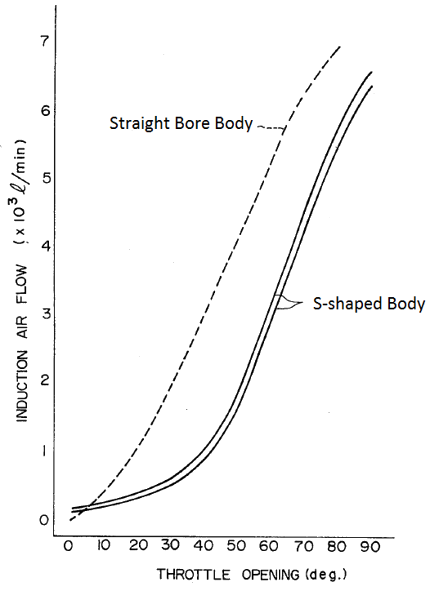
Figure 11. Flow vs. Angle response of Straight and S-Shaped throttle bodies

Figure 12. Overlayed CMM scans of aftermarket ported throttle bodies vs. OEM body.
Aftermarket ptb (Ported BODIES)
Reverse Engineering
Aftermarket ported throttle bodies (PTB) were made from new OEM parts. They are nearly identical to the OEM’s and within the spread of data measured on 10ea OEM’s except in the inlet region, where the forward offset bore was reworked as shown. Everywhere else the scans (points) coincide with the OEM contour (Cyan) as shown in figure 12.
Aftermarket PTB-A (red) was reworked by reducing the taper on “lip” from 60° to 45°. Then a .185 inch radius was added tangent to the taper and the ellipsoidal surface of the upper active contour.
This part appears to have been finished by wire brushing w/ a surface roughness of 125 microinches average. It is effective from 27° to 35°.
Aftermarket PTB-B (yellow) was reworked by reducing the taper on “lip” from 60° to 30°. Then a .160 inch radius was added tangent to the taper and the ellipsoidal surface of the upper active contour.
This part appears to have been finished by polishing w/ a surface roughness of 16 microinches average. It is effective from 20° to 35°.
Aftermarket PTB’s showed an improvement on over the OEM in the 25° to 35° range of throttle position, however, from idle and up to 25°, the issues persisted as it can be expected given the extent of this aftermarket modifications.
PTB-B showed better performance than PTB-A, also a consequence of the extent of the modification reaching further into the ellipsoidal contour and its better surface finish. None of the aftermarket throttle bodies modified the lower active contour on the outlet side of the valve body.
In summary, the active contours of all the reverse engineered parts perform as follows:
OEM: Idle to 30° is the baseline part throttle driving range. Transition to power drive is in the 30°-35° range.
PTB-A: Idle to 27° range is the same as OEM. Transition to power drive is in the 27°-35° range.
PTB-B: Idle to 20° range is the same as OEM. Transition to power drive is in the 20°-35° range.
PTB-C and PTB-D: Are very similar to PTB-A and were not added to the plot for clarity.


Figure 16. Aftermarket PTB-B, seen from outlet side and showing half-shaft modification.
Another feature shown on PTB-B is the “half-shaft” modification which is the removal of material by side milling the shaft on both sides of the plate as shown in figure 16. This modification increases the flow area of the throttle body at 90 (full throttle) and some aftermarket suppliers claim horsepower gains at full throttle.
It is important to note that at full throttle the manifold pressure is nearly identical to the pressure upstream the throttle plate (ambient in this case) and that the pressure drop in the air induction system is driven by the inlet valve. This fact can be easily verified by the readings of the manifold air pressure sensor (MAP) which in this cases indicates ambient pressure.
The effect of this increased area is proportional to airflow but the effect may be so small that can be considered negligible and it is most likely smaller than the resolution of sensors/instruments used to test them.

Figure 17. Throttle response of OEM and PTB-B.
Throttle response measurements
Mass flow rate and absolute throttle position data were streamed from the vehicle sensors for both the OEM’s and the best performing aftermarket PTB throttle valves.
Figure 17 shows that both throttle bodies respond nearly identical, slowly and linearly from idle (~5°) up to about 20° to 25°. After that and up to about 36°, the behavior of both curves is approximately exponential, with the PTB-B curve surpassing the OEM until both curves meet again right after the 36° mark and continue to march nearly identical up to 90° (full throttle).
This result confirms the observations made in the geometry of the parts when overlayed on each other, that is, the range of geometric modification coincides with the range on which the modified PTB-B air flow departs from that of the OEM.
CFD Simulations

Figure 18 shows the results of a CFD simulation of the OEM throttle body at 20° with a pressure differential across the plate of 101 kpa (1 atm) on the inlet side and 25 kpa at the outlet (manifold side). It can be observed that all the pressure drop occurs at the flow gap between the plate and the active contour where the air is choked and reaches sonic speed.
This sharp pressure drop across the plate clearly divides to very distinct zones, the inlet (red) on which the pressure is atmospheric and the outlet (cyan) which corresponds to the manifold pressure.
The predicted mass flow rate, in this case, is 25.3 g/s and closely matches that of experimental data obtained from vehicle sensors.
Because the flow is chocked, it does not respond to manifold suction, regardless of engine type (naturally aspirated or forced induction). It does respond to upstream pressure (ambient) but that is not a controllable variable. Only changing the throat area and the discharge coefficient of the gap can increase airflow to the engine.

Figures 20A and 20B show transonic flow at active contour interfaces where the area is the smallest. Large pressure losses occur at this point. It is clear why these contours are active while the rest of body internal geometry plays a negligible role.
SE8223-100 DESIGN
SOLER Performance
Instant power. Airflow/power gains start right of idle, no need to wait until the blade has reached 20 degrees or more.
Much more power at part throttle. We doubled the rate of change of mass airflow (MAF) from 1.2 g/s-deg to 2.4 g/s-deg.
Higher quality. We made sure every thousandth of an inch was accounted for, that our surface finishes were the best, we road tested openly and extensively, we bench test each unit.
Verifiable results. Don’t believe us, check our numbers, compare our quality.
Guaranteed to last. Made from new OEM parts, machined the latest in CNC technology, assembled with care and safety in mind.

